4. EXPERIMENTAL PROCEDURE
4.1. Practice 1: Experimental determination of drying curves of the sand
Objective
Our goal in this practice is to obtain drying curves.
Introduction
The objective of this practice is obtaining the drying curves and identify the critical period ahead and post critical period.
The function of a solid tray dryer is to remove water from the solid, without altering their properties. In this pilot plant is monitored at all times all the properties of temperature, humidity and air velocity and also the weight of the solid.
The following image shows the main parts of the instrument :
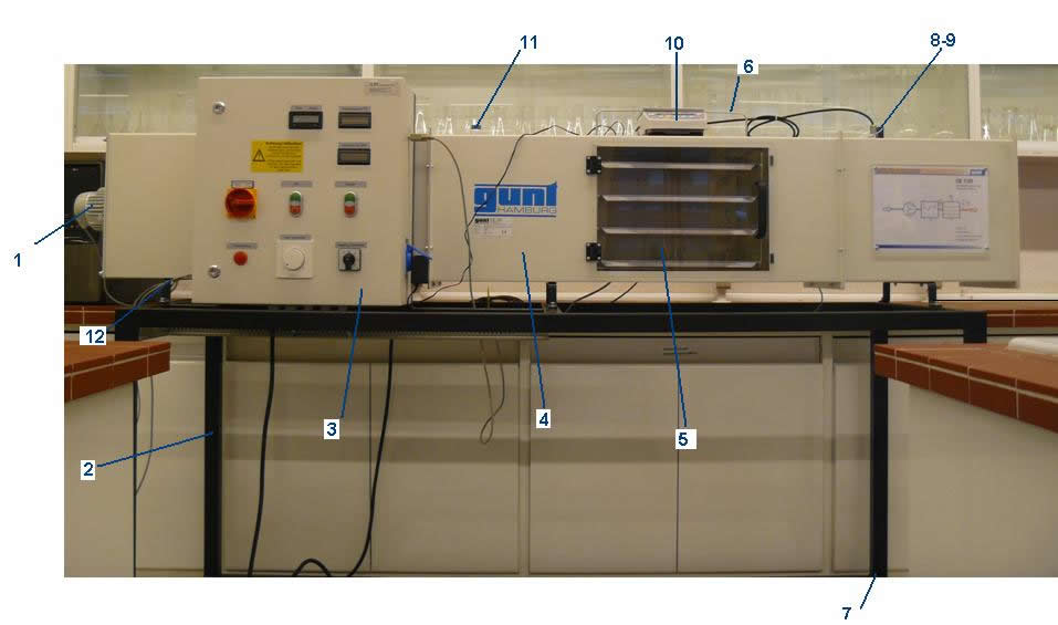
Where:
| 1) Fan |
5) Transparent window |
9) Temperature/ humidity sensor |
| 2) Cuirass |
6) Support material to be dried with frame |
10) Digital balance |
| 3) Control cabinet |
7) Bolt compensation |
11) Temperature T1- humidity sensor  1 1 |
| 4) Drying tube with windows |
8) Anemometer |
12) Heating connection |
The parts of the control cabinet are:
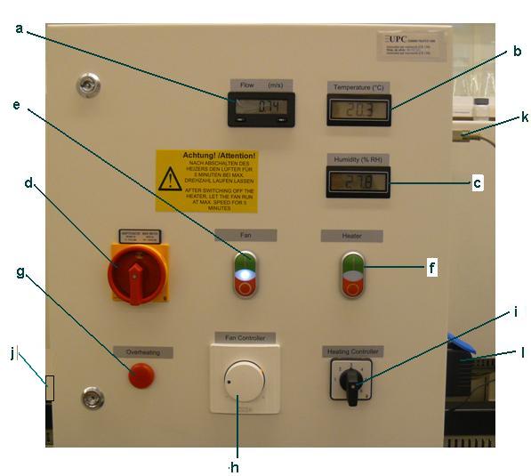
Where:
| a) Air velocity in the drying tube (m/s) |
e) ON/OFF fan switch |
i) Switch to gradual heating power |
| b) Temperature T1/T2 |
f) ON/OFF heater switch |
j) USB connector to record data with the computer |
| c) Relative humidity of air 1/2 |
g) Indicator of overheating |
k) Balance connection |
| d) Principal switch |
h) Control the number of revolutions of the fan |
l) Base the connector network
|
Materials
The materials used will be the pilot plant drying of solids, thickness 0-3 mm sand and distilled water.
Procedure
- Start the computer.
- Plug the balance with the computer.
- Turn the principal switch of the control cabinet in position ON.
- Start the balance by pressing ON switch and without trays, hum the balance.
- Put the trays one by one and record the weight of each, leaving them out of the device.
- Pressing the button twice to connect the fan position.
- Then selected revolutions fan turning wheel. As maximum can reach 950 rpm.
- After turn on heater with push button double in position ON.
- It selects power heating through switch stepped. As maximum can reach to 3500 W (step 7). Must consider not can run the heater with maximum power and fan speed minimum since heater be disconnected for overheating.
- It will stop the fan and the heater turned on until they reached constant conditions.
- Once arrived at the stable conditions recorded the value of airflow, temperature, and% relative humidity shown in the dashboard.
- Then the 4 trays filled with a layer of wet sand.
- We placed one by one to the frame, and note the weight of each separately.
- Once weighed, introduced the 4 trays and start the software to store data.
- The longer the drying process until constant weight.
- To stop the device, first of all disconnect the heater is putting the button twice in OFF position.
- It will leave about 5 minutes and then turned on the fan will stop putting it in position OFF.
- Removed the trays and cleaned carefully.
- Turn off the balance.
- Finally, disconnect the dryer from the wheel of the control cabinet by placing it in position OFF.
The following video can be seen in the experimental plant:
Processing results
In order to express the results as a table-type graphics will:
- For the solid curves refer to:
| Time (h) |
Wet weight solid (g) |
Water weight (g) |
Solid moisture (X) (g H2O/g dry solid) |
Humidity variation (∆X/∆t)
(g H2O/g dry solid·h) |
Rate drying (W)
(g H2O/m2·h) |
| |
|
|
|
|
|
| |
|
|
|
|
|
| |
|
|
|
|
|
| |
|
|
|
|
|
| |
|
|
|
|
|
| |
|
|
|
|
|
| |
|
|
|
|
|
Where : W=-(S/A)·(∆X/∆t)
- For the curves refer to the air:
| Time (h) |
Electric power heating (W) |
Temperature input (ºC) |
Temperature output (ºC) |
PHI_1 (%) |
PHI_0 (%) |
x1 (g steam/Kg dry air) |
Volumetric air flow (dV/dt) (m3/h) |
| |
|
|
|
|
|
|
|
| |
|
|
|
|
|
|
|
| |
|
|
|
|
|
|
|
| |
|
|
|
|
|
|
|
| |
|
|
|
|
|
|
|
| |
|
|
|
|
|
|
|
| |
|
|
|
|
|
|
|
Where:
PHI_1 is the relative humidity of air input.
PHI_0 is the relative humidity of air output.
In the theoretical foundations section is expressed by all necessary calculations and formulas to explain most of the concepts.